How Hollow Section Corner Radius Affects Tube Laser Cutting
Aug 1, 2024
1 min read
0
30
0
A common question in the tube laser industry is what corner radius should be used to model SHS/RHS parts for Tube Laser Cutting. The short answer we usually give is 1.5x wall thickness (WT), but there’s more to the story.
A lot of the CAD models we receive have been drawn with the manufacturers specification which can be up to 2.5x WT for the external radius. This may be technically correct, but in our experience with tube laser cutting it’s better to program the cutting path based on 1.5x WT (we usually adjust the model at the programming stage if required).
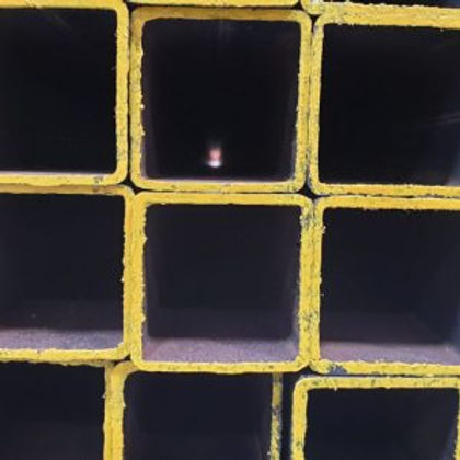
The difference lies in the fact that the corner radius doesn’t always meet the sides at a tangent as illustrated in the image. If we programmed the tube laser based on a 12mm corner radius it would start rotating the material too early, resulting in a potential nozzle collision and decrease in cut quality.
There can be small differences in the exact profile depending on the steel manufacturer, but we’ve found that using a corner radius of 1.5x WT gives consistent results and improves cut quality.


